Page 285 - 08-气源处理元件
P. 285

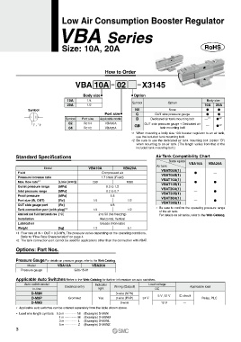
Low Air Consumption Booster Regulator


                                 VBA Series


                                Size: 10A, 20A


                                                     How to Order


                                      VBA 10A 02                       X3145


                                          Body size                Option
                                  10A       1/4                                                        Body size
                                  20A       1/2                   Symbol            Option            10A   20A
               Symbol                                               Nil             None               V     V
                                                     Port size      G         OUT side pressure gauge  V     V
                                 Symbol   Port size  Applicable model  B   Dedicated air tank mounting bolt  — *1  V *2
                                   02     Rc1/4      VBA10A        GB   OUT side pressure gauge + Dedicated air   *2
                                   04     Rc1/2      VBA20A                     tank mounting bolt     —    V
                                                                  *1   When mounting a body size 10A booster regulator to an air tank,
                                                                    use the included tank mounting bolt.
                                                                  *2   Be sure to use the dedicated air tank mounting bolt (option “B”)
                                                                    when mounting to an air tank. (The length varies from that of the
                                                                    included tank mounting bolt.)
         Standard Specifications                                              Air Tank Compatibility Chart
                                                                                     Booster regulator  VBA10A  VBA20A
                                                                              Air tank
                       Model                 VBA10A           VBA20A             VBAT05A(1)
          Fluid                                    Compressed air                VBAT05S(1)      V         —
          Pressure increase ratio                  1.7 times (Fixed)             VBAT10A(1)
          Max. flow rate *1   [L/min (ANR)]    230             1000              VBAT10S(1)      V         V
          Outlet pressure range  [MPa]               0.3 to 1.2                  VBAT20A(1)
          Inlet pressure range  [MPa]                0.2 to 0.7                  VBAT20S(1)      —         V
          Proof pressure      [MPa]                     1.8                      VBAT38A(1)
          Port size (IN, OUT)  [Rc]            1/4              1/2              VBAT38S(1)      —         V
          OUT side gauge port  [Rc]                     1/8
          Tank connection port (with plug) *2  1/4              1/2           *   Be sure to confirm the operating pressure range
                                                                                of the air tank.
          Ambient and fluid temperatures [°C]     2 to 50 (No freezing)         For details on air tanks, refer to the Web Catalog.
          Installation                            Horizontal, Vertical
          Lubrication                             Grease (Non-lube)
          Weight              [kg]             1.2              5.1
         *1   Flow rate at IN = OUT = 0.5 MPa. The pressure varies depending on the operating conditions.
           Refer to “Flow Rate Characteristics” on page 4.
         *2  The tank connection port cannot be used for applications other than the connection with VBAT.

         Options: Part Nos.


         Pressure Gauge/For details on pressure gauge, refer to the Web Catalog.
               Model         VBA10A           VBA20A
           Pressure gauge             G36-15-01


         Applicable Auto Switches/Refer to the Web Catalog for further information on auto switches.
             Auto switch model                  Indicator                 Load voltage
                 In-line         Electrical entry  light  Wiring (Output)     DC               Applicable load
                D-M9N                                     3-wire (NPN)
                 D-M9P             Grommet        Yes     3-wire (PNP)  24 V   5 V, 12 V  IC circuit  Relay, PLC
                D-M9B                                        2-wire              12 V       —
         *  Applicable auto switches can be ordered separately from the table shown above.
         *  Lead wire length symbols:  0.5 m  ………… Nil  (Example) D-M9N
                              1 m  ………… M  (Example) D-M9NM
                              3 m  ………… L   (Example) D-M9NL
                              5 m  ………… Z   (Example) D-M9NZ
         3
   280   281   282   283   284   285   286   287   288   289   290