
Page 287 - 08-气源处理元件
P. 287
VBA Series
Please use the Booster Regulator Model Selection Software on the SMC website: )
Sizing (https://mssc.smcworld.com/brmss/
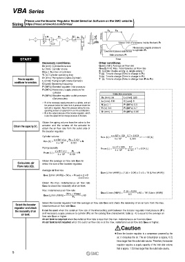
Tc Ts
Stroke
P1 P2 Lc
P3
øDc
Upper limit of pressure inside the tank P2
Pressure Lower limit of pressure inside the tank Necessary supply pressure
to cylinder P3
Inlet pressure P1
START Time
Necessary conditions: Other conditions:
DC [mm]: Cylinder bore size QAVE [L/min]: Average air flow rate
LC [mm]: Cylinder stroke QMAX [L/min]: Max. instantaneous air flow rate
N [pc.]: Number of cylinders K: Cylinder double-acting: 2, single-acting: 1
TC [s]: Cylinder operating time T1 [s]: Time to charge (Time to charge to P3)
T2 [s]: Time to charge (Time to charge to P2)
Provide requisite DT [mm]: Piping bore (Valve-Cylinder) T [s]: Time to charge (Time to charge from P3 to P2)
conditions for selection. LT [mm]: Piping length (Valve-Cylinder)
C [cpm]: Operating frequency
P1 [MPa]: Booster regulator inlet pressure
P3 [MPa]: Necessary supply pressure for
cylinder
P2 [MPa]: Booster regulator outlet pressure Selection example
(Set pressure) Dc [mm]: 50 LT [mm]: 500
LC [mm]: 100 C [cpm]: 6
* P3 is the necessary supply pressure to a cylinder, and set
the pressure below the lower limit of pressure inside the N [pc.]: 1 P1 [MPa]: 0.5
tank with a regulator. Adjust the pressure taking the max. TC [s]: 0.5 P3 [MPa]: 0.7
operating pressure of equipment in use into consideration. DT [mm]: 4 P2 [MPa]: 0.85
* P2 is the output pressure of the booster regulator, which
is also the upper limit of charge pressure to the tank.
Obtain the piping volume from the valve to the
Obtain the capacity (V). actuator and the volume of the actuator to
obtain the air flow rate from the outlet side of
the booster regulator.
2
Cylinder volume VCYL [L] = p x 50 x 100 x 0.7 + 0.101 x 1 = 1.55 [L]
2
p x DC x LC P3 + 0.101 4 x 10 6 0.101
VCYL [L] = x x N
4 x 10 6 0.101
2
Piping capacity VTUBE [L] = p x 4 x 500 x 0.7 x 1 = 0.04 [L]
2
p x DT x LT P3 4 x 10 6 0.101
VTUBE [L] = x x N
4 x 10 6 0.101
Obtain the average air flow rate QAVE to
Calculate air select the size of the booster regulator.
flow rate (Q).
Average air flow rate
QAVE [L/min (ANR)] = (1.55 + 0.04) x 2 x 6 = 19 [L/min (ANR)]
QAVE [L/min (ANR)] = (VCYL + VTUBE) x 2 x C
(Reciprocation)
Obtain the max. instantaneous air flow rate
QMAX to check the necessity of an air tank.
Max. instantaneous air flow rate (1.55 + 0.04)
(VCYL + VTUBE ) QMAX [L/min (ANR)] = 0.5 x 60 = 191 [L/min (ANR)]
QMAX [L/min (ANR)] = x 60
TC
Select the booster regulator from the average air flow rate QAVE and check the necessity of an air tank from the max.
Select the booster
regulator and check instantaneous air flow rate QMAX.
the necessity of an It can be used when the outlet air flow rate of the intersecting point between the booster regulator inlet pressure (P1)
air tank. and necessary supply pressure to cylinder (P3) on the catalog flow characteristic table (p. 4) is equal to the average air
flow rate QAVE or higher.
An air tank is required when the outlet air flow rate is less than the max. instantaneous air flow rate QMAX.
An air tank is not required when the outlet air flow rate is at the max. instantaneous air flow rate QMAX or higher.
Caution
¡Since the booster regulator is a compressor powered by the
air, it consumes the air. The air consumption is approx. 0.72
times larger than the outlet side volume. Therefore, the booster
regulator requires a supply capacity of the inlet side volume
that is approx. 1.72 times larger than the outlet side volume.
5